Reconstruction of mill-roll lathe electric drives in Roll shop of
1700гп Mill
Customer: JSC “Arcelor Mittal Temirtau”, Temirtau
Reconstruction Object: Roll-turning machine model 1827C at Roll shop area in mill 1700 гп
RECONSTRUCTION OBJECT SPECIFICATION
Roll-turning machine model 1827С (picture No1) is used for effective lathe
work of iron and steel rolls at rolling mills in metallurgical industry. The machine also can be
sed for lathe work of long parallel details to remove surface defects, formed during the casting process,
rolling or swaging. Roll processing can be made with cutting tool with plates from high-speed steel or hard metal.
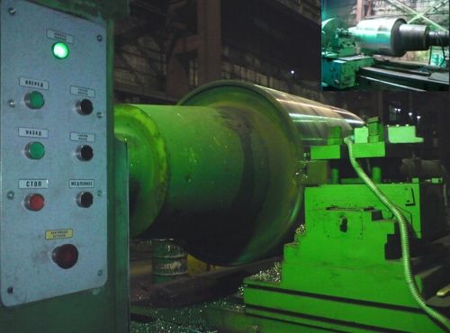
Picture No1 mill-roll lathe model 1827С
The machine consists of following units:
- foundation slab
- head stock
- dead head
- carriage
- apron
- feed box
- back-rest
- chip box
- electrical equipment
Head stock consists of the following:
- the main electric drive
- gearbox
- axial drive
- hydro-changeovers
Main machine data:
- roll maximum length is 6500 mm
- the biggest diameter of roll body is 1650 mm
- the biggest weight of workpieces is 50000 kg
- blades number in the blade holder is 1 piece
SOLUTION AND AUTOMATION SYSTEM CHARACTERISTICS
A spindle drive is realized by DC electric drive having power 110 kW, 220 V, 300/1200 rpm, powering from the control
irreversible converter of the firm “SIEMENS”. SIMOREG DC MASTER 6RA70 is complete thyristor electric drive, representing cabinet-type facility
of one-sode service, consisting of the thyristor converter module with microprocessor control and auxiliary equipment: switching equipment,
fuzes, power sources, automatic circuit breakers, contactors, interposing relays. DC 600 А converter is irreversible; change of motor rotating
direction is carried out by field revers control. Speed regulation without feedback is carried out by rotating speed with field reduction in four times.
Using of internal intensity setting device provides machine soft start and soft speed change during the work. It is anticipated dynamic breaking mode.
There is single-line diagram of the electric drive on the picture No2.
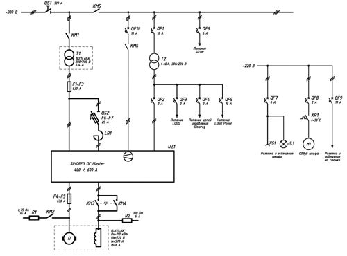
Picture No2 A single-line diagram of the electric drive
Machine control logic is implemented with the help of programmable module LOGO 230RC of the firm “SIEMENS” with expansions
of digital inputs/outputs DM8 230RC and additional software S00 of the converter SIMOREG. Control buttons are situated on the headstock body
and duplicated on the carriage (picture No1).
A transmission gear has three mechanical levels: 0-4 rpm, 0-16 rpm, 0-64 rpm with hydraulic shifts with the help of
two-sided hydraulic cylinders and compound-lever arrangement, which is situated inside the transmission gear. For the selected level
control and number of spindle rotation on the headstock it was installed operator’s panel OP73, represaented on the picture 3.
There is anchor current and excitation current of the main electric drive.
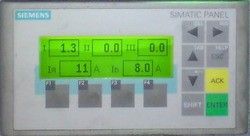
Picture No3
Operator’s panel OP73
A green indicator on the headstock (picture 1) shows the rgight chosen level, which there is in the
blocking and protection circuit. It is anticipated warning, emergency, light and sound signalling by control system on the machine.
Project implementation period
Project implementation period is 2 months, commissioning is March, 2008