Modernization of gas boosting station-2,3 Technological Process Automatic control system of
GBS-2, GBS-3 JSC “Arcelor Mittal Temirtau”
Gas boosting stations (GBS) are destined for mixed gas supply (blast furnace + coke gas) to rolling-mill shops of the plant. Outlet mixed gas should be in compliance with pre-set parameters in terms of pressure and correlation (calorific value). In order to meet this requirement the station is fitted with gas boosters of series 1050-12-1 and electrical actuators for regulating throttle valves, that are installed on gas pipelines (BF and coke gas), as well as on bypass line.
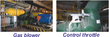
Figure 1
Necessity for monitoring and control system modernization appeared for the reason that operating equipment morally and physically went out of date at that moment. Monitoring and control systems didn’t correspond to ES norms “Industrial safety requirements at gas facilities of ironworks”. Most operations on mechanism control were run in manual mode, indication and signaling control systems didn’t fit modern requirements of human engineering. A high percentage of human factors in control reduced either quality of delivered gas or reliability of the station work.
All available actuators had been changed to new ones of series «AUMA» during modernization. Revision of regulatory valves either at main gas pipelines or gas boosters was carried out.
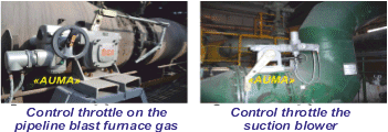
Figure 2
Gas booster and mechanism common control systems were built with using microprocessing units on the basis of Siemens programmable controllers S7-300.
Reliability improvement is realized automatic control switching over to reserve controller if failure and faulty operation of basic elements is happened.
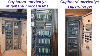
Figure 3
Visualization was carried out at two independent identical SCADA systems (with software WinCC). System permits an operator at his working place to get required and reliable information about booster and station work on the whole, including gas pollution at separate sites of the station, as well ambient temperature. There is light and sound signaling, warning operating personnel about parameter output for specified limits and emergency situations. Light and sound signaling by exceeding of MPC gas works separately.
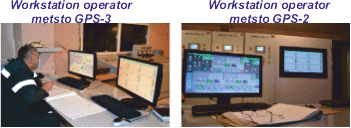
Figure 4
An operator gets working parameters of the station in digital form and in the diagrams. An operator can change settings of regulated parameters and control their processing at the same time, change control modes (automatical-manual) from his working place. An operator operates by actuators manually through SCADA system or using buttons on automation cabinets.
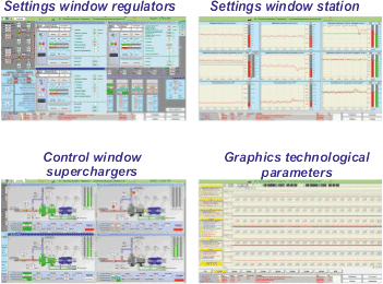
Figure 5
Station work can be viewed (controlled) for any time period, using archive data. Information is given in the form of schedules and message tables at monitor screen; as well this information can be printed. Regulator setting parameters can be changed by means of SCADA system, and their work can be controlled at temporary schedules. Access to this operation is possible using special access password.
Each gas booster has control system, which provides as follows:
- automatic motor start and cut off;
- valves control according to preset start and stop program;
- light and sound restarting signaling in the operator room and directly from booster.
System controls as follows:
- bearing temperature,
- oil temperature and pressure in oil system,
- temperature, pressure and water flow rate,
- air temperature and pressure,
- booster vibration,
- inlet and outlet gas parameters (temperature and pressure).
Interlocking system doesn’t permit to switch on boosters at nonobservance of required conditions and switches off booster at situations which can lead to the accident. Boosters are switched off according to the signal from general control system at emergency situations on the whole at the station or gas pipelines.
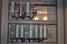
Figure 6
Common control system provides as follows:
- processing and collection of station work;
- automatic pressure regulating in outlet and inlet collector;
- maintaining of BF and coke gas expense ratio in accordance with pre-set calorific value.
- special programs, providing required control algorithm for throttle valves and calculation of the required gas expenses according to calorific value were developed for implementation of automatic control.
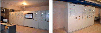
Figure 7

Figure 8
“RVSA” Ltd. had carried out designing and installation works, fabrication of complete control cabinets, development of PLC programs and SCADA systems, adjustment and commissioning. Experienced and working system operation at GBS-2 and GBS-3 showed high reliability, efficiency and serviceability. System has received positive opinion not only from operational personnel of the station but also from technical direction of JSC “Arcelor Mittal Temirtau”.


