Automated system of emergency power supply and control of actuators at gas facilities of Karaganda Steel Plant JSC "ArcelorMittal Temirtau"
The purpose of BF gas distribution system
BF gas collector, representing a pipe with length - 800m and diameter - 3,02m, is destined for BF gas gathering and dispersion according to consumers. Gas sources are four blast furnaces, connected to collector through gas-cleaning units. Consumers are thermal and thermo-technical plants.
The collector contains about 6000 cubic meter of fire and explosive gas under pressure in 1000 millimeter of water.
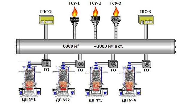
Figure 1
Excessive increase or decrease of gas pressure is emergency situation at the collector.
Pressure below a critical (300 millimeter of water) is very dangerous, i.e. Condition of air and coke gas inflow occurs. As a rule it leads to formation of explosive mixtures. There is high probability of explosion with serious collector and other communication damages.
As A rule pressure increase leads to:
- actuation of protective hydraulic valves
- al collector depressurization.
Solving of problems noted above requires time and material expenses.
The main reason of emergency situation appearance is serious deviations from normal work of sources and gas consumers or their accidents.
The most serious case is considered power failure at the several sites of gas facilities at the same time i.e. in this case:
- It is impossible quickly and centrally to operate mechanisms, distributed at large area.
- Information about current technological parameters, condition of locking and regulating equipment is missing.
- As a consequence it is difficult to take adequate and operative decisions to stop accident development.
The construction concept of emergency automation system
Reservation is provided by automatic transfer switches with uninterrupted power supply unit (UPS).
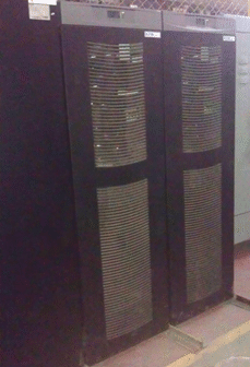
Figure 2
ATS provides uninterrupted work even at full loss of power supply from external sources, i.e. in this case UPS supporting power in the cabinets: control instrumentation, visualization system, regulating and stop valve control system is connected.

Figure 3
Uninterrupted power supply units are installed in the cabinets with electronics additionally, which provide system work at the time of ATS input switching.
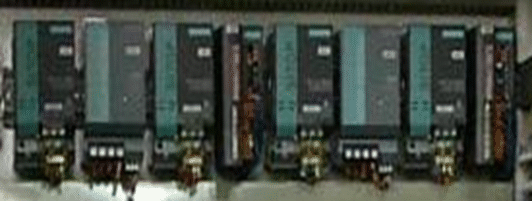
Figure 4
Power supply diagram provides:
- input switching time no more two seconds
- required power supply of actuators from UPS is suitable for equipment safing under full supply disconnection.
- continuous work of visualization and monitoring system (PLC, remote stations, servers and operator stations) during 3 hours no less
- prolonged period of technological parameter collection, display and control.
Hot sparing of monitoring and control system
Process control algorithms are carried out by means of controller «S7-414H» from «SIEMENS» production. Main and reserve modules work in hot reserve. Switching between modules is realized not more than 70 ms.. It allows carrying out the repair, service and adjustment operations without system stopping at one of modules.
Server pair and two client stations are installed in PLC cabinet. Server pair provides parameter logging for the year.
Client stations make continuous control of mechanism work, signaling and visualization of current situation.
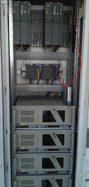
Figure 5

Figure 6
Readiness and monitoring control of non-reserved units and mechanisms is realized.
So, in the electric drive control scheme of stop valves it is provided as follows:
- continuity test of cable routing
- working order control of drive electrical part
- limitation of motor starting current
- overload protection to the mechanism
- overcurrent protection of the motor
- limitation of drive motion using end switches.
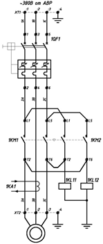
Figure 7
Visualization and signaling system
Technological process data are printed on the screen of two client stations and terminal. It permits to estimate condition of all equipment, its work operatively, to control technological parameters.

Figure 8
It permitted to eliminate strikes in mechanical transmissions, to achieve soft regulation of gas flow through gas-waste device and to activate functions of electronic converter protections.
Pressure value is controlled by six sensors. Inaccurate measurement is excluded from calculations with the help of program. Sensor fault is displayed on the screen of client stations and terminal.
Measurement accuracy and control reliability allowed improving the quality of blast-furnace gas pressure regulation in the collector.
An operator can select his required object for detailed observation and control separately for each station. Visualization and control system was carried out using SIEMENS programming package PCS7. Improve elements of stored information supplying were developed.
Average and total values of technological parameters per hour, twenty-four hours, week, and month are kept in the production book. Data scanning is possible for previous three years.
Every mechanism condition, interlocking and protection work is displayed in separate windows. Their review is available at any time by “mouse” clicking on the element icon.
After authorization of “engineer” level it is available as follows:
- change of the warning and emergence signaling system limits,
- change of technological parameter measurement scale,
- sensor disconnection.

Figure 9
Drive control of stop valve can carry out remotely from operator screens of client stations.
The main system design principle was striving to give operator complete information and to help personnel to make and execute decisions quickly.
For this purpose distant control is set in the program of all units.
Gas discharging facilities (flares) are fitted with automatic ignition system with flame control sensors.
Information about ignition system work and control is available to the operator from client stations.
Possibility of control system development.
Control system project assumes remote centralized mechanism control.
This function can be also activated along with installation of new mechanisms and shut off valves.
Connection points are laid for signal change with adjacent productions:
- coke-chemical
- blast-furnace
- converter
- rolling.
There is access to control system through local information network and Internet.
Connection of new units and plants without increasing powers of main system through connection point adding can be done to field bus bar of controller “PROFIBUS”.


