|
|
Kok Tobe rope way drive control system
Customer: “Park Kok-Tobe”, Ltd., Almaty
Optical sensors BERO are used for accurate carriage arrival to the station and automatic correction of determined carriage way (spring compensation during road commission and temperature effect). During the reconstruction some changes were made in kinematic chain; in this case safety locks and stops chain is saved. Available service break was dismantled due to the fact, that a new motor of Siemens was dismantled due to the fact that new motor of Siemens with power 160 kW had optically in-built electro-magnetic plate brakes with manual release function. 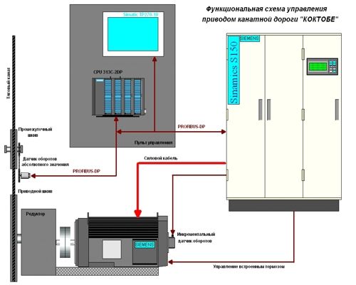 Picture No1 New operator’s pulpit not only changed its size but it became more compact; Carriage movement control saved operator’s procedural path because of it operators could work with new control system without any problems. At the same time, after modernization some buttons on the pulpit were deleted, because they became needless. Operator’s actions at system assembly are blocked up with buttons ‘emergency stop’, ‘drive demounting’, carriage movement joystick is not zero position and key tag is in prohibiting position. Conditions of the drive, interlock circuits, warning and carriage position can be watched on the operator’s panel. Operator’s panel has several windows. The window “Operator” serves for visual display of drive conditions, carriage movement speed, drive current, carriage movement direction, carriage positions and carriage distance concerning to the upper station. When frequency drive Sinamics S150 was implemented, control system permits to carry out speed task directly from the operator’s panel. There are two drive work modes for the ropeway. This is Working mode, permitting to work at speeds which are equal to working ones (full speed is 6, 3 m/sec) and Switching mode, permitting to work at low speeds without working mode change. Minimum speed, at which the ropeway works after drive modernization, is 0,05 m/sec. and maximum one is 7 m/sec. 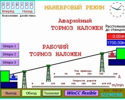 Picture No2 It’s possible to select the window Support on the operator’s panel, where you can consider carriages arrival to the concrete Support place. Moreover, carriage distances to the station, drive current, direction of carriage movement, carriage position on the support and carriage driving speed are displayed either in operator’s window or in support window. It’s possible to enter in the bypass window from any windows, here it is observed readiness of safety lock chain and in the case of carriage overwind and runover on emergency limit switch, in this window it was foreseen emergency interlock bypass by one from limit switches for carriage cross over from emergency limit switch. 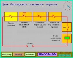 Picture No3 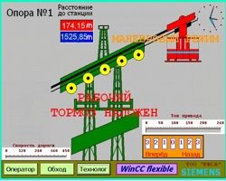 Picture No4 Also it is possible to exit in the window Technologist from any window. It’s possible to look through required speed modes for the Working mode and Switching mode, also to change actual mode. From the window Technologist there is exit in additional window, where it’s possible changing of speed mode, manual zero filling of carriage position, counter device of journey number and interlock speed bypass function for adjustment. After modernization of ropeway drive control system all sound and lamp signaling were realized according to the commission requirements. In accordance with technological task, control system provides soft carriage arrival and departure from the station in the automatic mode, but an operator has control priority, he can take control on himself at any time. Until modernization heating of ballast resistors in the circuit network during drive movement, it led to additional losses of electric energy. Using of the modern frequency converter Sinamics S150 on this drive with the recuperation possibility permited to reduce active power consumption and to stabilize reagent, because cosine is installed in the compensation mode which equels 0,96. Using of additional switching motor during preventive measure and repairs on this system became illogical. Therefore switching motor is used in emergency cases at energu tripping and the work from field ion source. |
www.rvsa.kz www.rvsa.ru
|