Modernization of converter turning electrical drives
The customer: JSC “ARCELOR MITTAL TEMIRTAU”, Temirtau.
Technological process specification
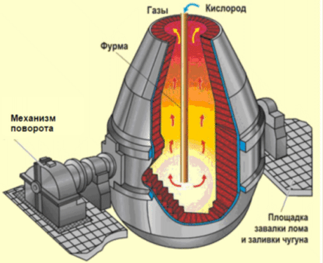
Converter is destined for steelmaking from hot metal and burden under oxygen blowing. The lead unit of oxygen-converter plant is converter with oxygen lances. Converter is a cylindrical vessel with narrowed part at the bottom, which is made from iron plate with firebrick lining inside it. The top of converter has a mouth and hot metal is overflowed through it, then burden materials are loaded and slag is poured off. Steel is poured off through outlet at the top of converter.
Three converters are installed at oxygen-converter plant of JSC “ArcelorMittalTemirtau”, the volume of each converter is 300 tons.

Figure 1. Basic oxygen converter
Converter turning unit has DC drive, carried out according to the scheme “generator-motor”. Four DC motors DP-92 of independent excitation with power 135 kW are installed on each converter device. Two motors are installed from each side of the converter. Electromechanical brake is mounted at the end face shaft of each motor.
Motor anchors get power supply from DC generator MP152-8Ê with power 750 kW.
Synchronous motor with power 1000 kW rotates DC generator. Current control of generator excitation changes motor rotation speed according to this scheme.
Electric motors are connected to the mechanism through two-stage spur-gear speed reducers.
Also there is reserve system generator-motor “synchronous motor – DC generator”, destined for converter motor power supply during emergency situations.

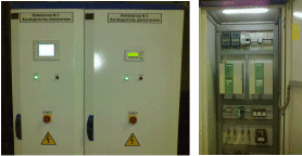
Figure 2 The appearance of control cabinets
Each converter turning electric drive control is carried out from three control units. Speed task is carried out step-by-step, with the help of cam controllers.
Before reconstruction generator excitation power supply was realized from thyristor converters VUK-50, made in 1969. Analog tachogenerators were used as feedback sensors for speed controllers. Due to wear of mechanical components there were cases of feedback breaking, led to converter overturning and serious losses.
Motor excitation was realized from unregulated source 220 V.
Requirements to control system
Converter turning mechanism is more important unit part. Therefore the following requirements impose to it: reliability, uptime, simple design, and variable speed capability widely.
Reconstruction goal:
- replacement of physically and morally worn-out equipment of motor and generator excitation systems;
- realization of reliable and effective reservation system;
- realization of regulated drive without electromechanical feedback sensors to improve reliability and decrease the probability of emergency situations;
- reconstruction of electric drive relay control circuits.
Solution and control system characteristics
During reconstructions it was carried out as follows:
- DC generator exciters were developed and implemented. Exciters are complete devices of cabinet execution. The main element is DC reversible converter Simoreg DC Master with nominal current 60 A. Switching equipment SIEMENS, galvanic isolation modules SIMEAS T, power supplies SITOP were used. Operating mode and main parameters indication on each generator exciter was carried out with the help of operator’s touch panel ÒÐ-177. Electric drive operation algorithms were implemented with the help of embedded program functions of converters Simoreg. Electric drive is made without external speed sensors (with feedback EMF). At that required accuracy of output parameters maintenance on the whole speed control range was provided.
- Drive exciters were developed and implemented. Each exciter includes two nonreversible thyristor converters Simoreg DC Master with nominal current 30 A (motors are divided into two groups by two pieces. Excitation of each motor group is carried out from single converter). Switching equipment SIEMENS, galvanic isolation modules SIMEAS T, power supplies SITOP were used. Operating mode and main parameters indication on each motor exciter was carried out with the help of operator’s panel OP-73. It was realized stepless load balancing system for motor anchors through excitation current regulation of motor groups.
- Converter turning drive reservation system was realized.
- Reserve generator and motor exciters were made and implemented. Developed system allows realizing 1) reservation of generator exciter for any converter; 2) reservation of motor exciter for any converter; 3) reservation of system generator-motor for any converter on the whole. Switching in reservation system is carried out with the help of crossover disconnectors and detachable joints in control circuits. Module LOGO 230RC was used for required blocking implementation.
- Control circuits were reconstructed. Drive control logic of each converter turning was realized using modules LOGO 230RC; by that available control circuits were essentially minimized, electromechanical relays were dismounted.
Works were carried out in volume:
- project development;
- electrical installation work
- commissioning work;
- guaranty support.
Implementation work was carried out in short terms during processing equipment repair.


