
|
|
THE EXCITER FOR TURBOGENERATOR
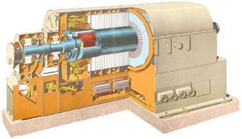 Picture No1 In Kazakhstan, for this purpose excitation systems are mainly used and produced by enterprises of Russia, Ukraine and a number of foreign companies, such as ABB. At the present time Kazakh Company “RVSA” Ltd. can offer exciters for generators of its own design and manufacture under the brand “Made in Kazakhstan”. “RVSA” Ltd. has experience in implementation, adjustment, repair and technical maintenance of excitation systems at several power plants of Kazakhstan: Karaganda TPP-TBS JSC “Arcelor Mittal Temirtau”, Topar State District Power Plant “Kazakhmys Energy” Ltd.; Petropavlovsk TPP-2 JSC “SevKazEnergo”; Rudny TPP JSC “SSGPO”; Balkhash TPP «Kazakhmys Energy». The exciter for synchronous generator of “RVSA” Ltd. has the grading CRV-STG-AAA/BBB on currents (AAA) 800-1000-1250-1600-2000 À, and voltage (ÂÂÂ) for the specific generator according to the customer’s request as indicated in the questionnaire. The exciter satisfies GOST 21558-2000 requirements, the best technical solutions, applied to the exciters of other manufactures are considered in it, also the work experience, gained over recent years during adjustment and implementation of excitation system is used. The device relates to the class of one group exciters with parallel self-excitation, its energy source is the stator voltage of the excited synchronous machine. Main functional units (Automatic excitation regulator, measuring device of electrical parameters and control system of thyristor rectifier, protection units and so on) are made, with the using of the microprocessor technology. Power supply of the elements for this device is realized from a few (up to three) independent sources of voltage. To carry out adjustment work, testing, characterization of idling and short circuit, the device is switched to the independent excitation mode, receiving power from the built-in power supply, which is not connected with voltage of this synchronous machine. All main units of the system are redundant and operate on the principle "each with each" due to cross-connections between devices. 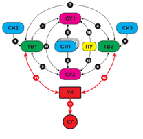 Picture No2 Excitation control from Main control Board is realized by means of the pulpit, equipped with switching and visualization bodies as operator’s panel and signal fixtures. The connection between pulpit and exciter is possible not only on fiber optic cable - channel of remote control but also on control cable – distance control. The type of the connection in each case is determined by the customer in accordance with the questionnaire. 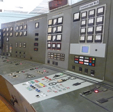 Picture No3 The compact design of the exciter meets the requirements of serviceability, adjustment, installation and dismantling of separate assembly units. During the modernization and reconstruction the exciter can be mounted in the power control rooms with limited working area, for example, in the existing power control room of the field breaking switch. Safety requirements in the operation of electrical installation are observed. 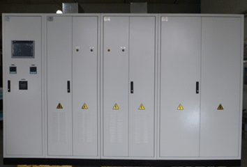 Picture No4
Devices and elements of the general purposes, mass-produced are used to the maximum. It permits to change components of other modifications or to the similar products of other manufactures if it is necessary. In general the exciter contains SIEMENS equipment, such as: thyristor rectifiers SINAMICS DCM, master controllers SIMATIC S7, measuring devices of electrical parameters SENTRON PAC 3200, protection units SICROWBAR DC, visualization and diagnostics equipment and protection terminals. The reliability and efficiency of this equipment is confirmed by long-term experience of its operation in various industries including the energy sector. A pulpit, which is integrated into the overall SCADA system, a power transformer, the cabinet of generator protections with units SIPROTEC, made by SIEMENS in combination with the exciter are supplied optionally. Integrated visualization system allows monitoring current parameters as schedules, tables and diagrams, conditions of all system units, not only in real-time mode but also on data from the archive for any period of time, it permits detect and analyze failures in the power grid and generator quickly.  Picture No5 Automatic excitation regulator system provides work of the exciter in manual and automatic modes with controlling of stator voltage, reactive power and power factor. The exciter has a system stabilizer PSS, which suppresses oscillations of the rotor and the generator electrical parameters during disturbances in the electric power system. Control of electrical parameters is made on a combined principle with the PI and PID adaptive controllers (with variable coefficients) thus high accuracy and performance during maintaining of marginal stability achieve. All basic operations: field injection, cutting into mains, networking, unloading and transfer to work from the external backup excitation can be carried out in automatic mode; it eliminates errors connected with human factor. Interlocks and protection units against switching overvoltage, limitation of operating parameters, built-in protection of the converter from the critical situations, the indirect calculations of the rotor temperature protect the converter and the associated generator from damages. The exciter is equipped with automatic characteristic measuring of idling and short circuit, using an auxiliary supply of power bridge voltage at disconnected converter transformer. Switching of the exciter to auxiliary power supply allows testing the equipment, when the turbine is stopped. 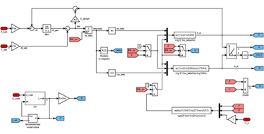 Picture No6 The mathematical model of the generator is built in the control program, it allowed to obtain a combined (math + physical) model of the excitation system in combination with the real exciter and thereby to test control system and converter, loaded on equivalent load or the generator rotor. Operation of all regulators, limiters, PSS operation, thyristor converter, power circuit, measuring characteristic program of idling and short circuit are verified during the testing in real-time. Using this model, it is possible to provide training of the operating staff during the work and maintenance of the excitation system. Excitation system passes a thorough and comprehensive test after assembly and its long-term operation is guaranteed. |
www.rvsa.kz www.rvsa.ru
|