Implementation of excitation system SST-2000-250-2,5 for turbo-genirator-3 at TPP-TBS
Data of modernization object
Turbo-generator TVF-63-2EU3 is destined for electric power generation through direct connection with steam turbine at heat power plant.
Generator has hydrogen forced cooling of rotor winding. It is thyristor excitation system of parallel self-excitation.
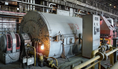
Figure 1
Generator specification:
- tator voltage – 10,5 kW
- otal power – 78750 kilovolt-ampere
- Active power – 63000 kW
- Stator current – 4330 A
- Rotor current – 1815 A
- Rotor voltage – 202 V
- Power factor cos? – 0,8
- Efficiency coefficient – 98,3 %
- Frequency of rotation–r/min
Reconstruction argumentation of excitation system
- Physical and moral equipment wear
- Lack of spare parts
- Human factor availability at the time of switching on generator in the network
- Little informative, outdated control and visualization system
Excitation system SST-2000-250-2,5
Excitation system is destined for DC power supply of turbo-generator excitation winding in normal and emergency modes of generator work with hot spare possibility.
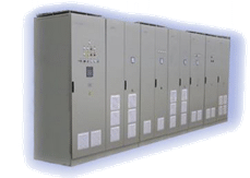
Figure 2
Excitation system provides:
- switching on generator in the network with the help of precise automatic or manual synchronization
- excitation and breaking of generator field
- manual operation with maintenance of given excitation current
- automatic operation with maintenance of given stator Cos?, Q or U
- unaccented transient modes in generator excitation control
- two-times forcing of excitation current
- protection from stator overvoltage
- stator and rotor current limit
- reactive power control and limit
- insulation resistance control of rotor circuit
- protection of excitation transformer and etc.
Structural control scheme
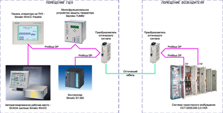
Figure 3
Programmable controller Simatic S7-300 uses for organization of data collection and processing for excitation system work, generator protections. Data transfer is realized through digital bus Profibus DP.
Connection between equipment of the main control board and exciter is carried out through the optical channel with the help of cable. Conversion between optical channel and electrical one (RS 485) is carried out with the help of modules OLM (Optical Link Module).
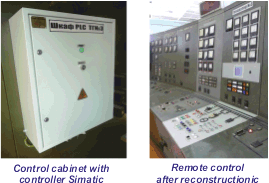
Figure 4
Visualization system
Visualization is made on the basis of personal computer with installed software Simatic WinCC.
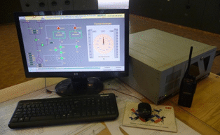
Figure 5
Working area of visualization system is shown by four main windows:
- “The main one”,
- “Oscillograms”,
- “Indication”,
- “Messages”
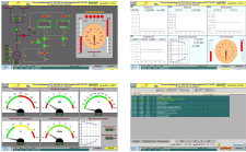
Figure 6
The main window shows current status of excitation system.
“Oscillograms” window is destined for diagram display.
“Indication” window shows current parameters as devices.
“Messages” window shows current and archived messages.
Six-inch color LCD operator panel is installed on the central pulpit of the main control board.

Figure 7
Visualization system provides as follows:
- display of current generator parameters.
- registration of informational, warning and emergency message.
- technological parameters charting (generator and mains voltage, generator and mains frequency, generator excitation current and voltage etc.)
- display of exciter condition
Generator protection unit Siprotec
Multipurpose microprocessor unit of generator protection Siprotec 7UM62 is installed instead of existing sets of relay protection during modernization.
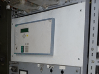
Figure 8
Siprotec provides all functions, required for generator, motor and transformer protection.
All unit functions are adjustable, they use for small, average and big generator protection.
Conditioning and ventilation system
The exciter room includes for climate control system.
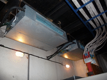
Figure 9
Power transformer is separated from exciter with thermal screen and provided with ventilation system.


